![]()
I have recently included a page about AF amplifers for use with Homebrew rigs. In this I mentioned that I may include a practical one-watt circuit, complete with PCB foil and layout. Here it is, but I have taken the liberty of engineering it to provide 4-watts of AF output and with a frequency response almost suitable for Hi-Fi applications.
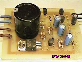
The circuit is very simple and incorporates darlington output transistors that will provide more than enough output current than is needed to drive a 3-ohm speaker. The gain may be pre-set for a variety of input levels, making it suitable for amplifying computer and cassette-deck Line-output levels. The input level is also suitable for use with the TDA7000 receiver. All components are easily available and I will shortly be making this project available as a kit. Naturally, the project will be built on a PCB which will also be available separately. Here is the first PCB, assembled and working.
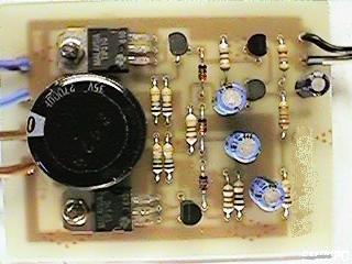
The completed unit is 60mm x 75mm and only 30mm deep. The depth could be reduced to 10mm if the output capacitor is mounted at the speaker and the on-board electrolytics are mounted horisontally. Here are the typical performance figures that may be expected from the finished amplifer using a 3-ohm load with a 13.8-volt supply. I see no reason why the supply voltage cannot be increased a little to obtain more output power:
| Parameter | Minimum | Maximum | Units |
|---|---|---|---|
| Supply voltage | 8 | 15 | volts |
| Output power | - | 5.4 | Watts |
| I/P for full O/P | 30 | 4000 | mV (RMS) |
| Noise O/P no I/P | - | 0.0005 | Volts RMS |
| Supply current (no-signal) | - | 50 | mA |
| Supply Current (Full O/P) | - | 1.9 | Amperes |
| 3dB Frequency Response | 42 | 34000 | Hertz |
| 6dB Frequency Response | 21 | 62000 | Hertz |
| Distortion at 2-watts | - | 0.01 | % (Vgain=10) |
![]()
No heatsinking is required for the output transistors when running at a modest output level with either speech or music. A small heatsink should be fitted to the two TIP41 transistors if running a constant tone level. The heatsink could be bolted directly to the TIP41s without electrical isolation if the heatsinks are not going to touch anything. A heatsink with a 15-square surface area is all that is required. Here is the circuit of the amplifer.
The gain of the amplifer is set by selecting the value of the feedback resistor (Rf) on the PCB. The value of Rf is equal to 1+(4700/Vgain) where Vgain is the voltage gain required. 4-volts RMS is the full-output level. Here is a guide for selecting the resistor.
| Value | Vgain | Typical use |
|---|---|---|
| 22K | 3 | 1300mV RMS - High levels (Small radio speaker) |
| 4K7 | 11 | 400mV RMS - e.g. computer/tape-deck Line-out |
| 1K0 | 48 | 80mV RMS - e.g. from TDA7000 RX |
| 330R | 143 | 30mV RMS (e.g. from microphones) |
The distortion and noise levels may increase at higher gain levels, but the test board was measured with Vgain = 10 and was driving a 3-ohm car Hi-Fi speaker. With higher-impedance speakers the frequency response will become wider but the output power will reduce a little. There was no trace of instability throughout the AF range and up to 150KHz so I thought it unncecssary to include a Zobel network. Incidentally, four-watts of AF will have the wife banging on the workshop walls, so do not underestimate QRP AF!