
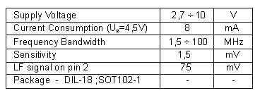
The face that FM receivers operate on pretty high frequencies makes their practical realization somewhat difficult, but most of the problems, as in many other amateur builds, originates from building the coils, except the self-bearing, small-inductance coils (without the coil body), which are easy to make, especially if there aren't many of them in the device and if no special instruments are required for setting up their proper inductance value. The coils used in this FM receiver are just like this, and there are only two of them, making the practical realization much easier. The basic data about the famous Philips' IC used in this project, TDA7000, are given in the following table.
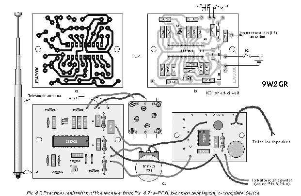
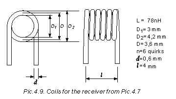
Electronic diagram of the HF part of the device (from antenna to the LF output) built with TDA7000 is shown on Pic.4.7. As one can see, it is a simple device, made with relatively small number of components. The IC contains all the stages of the superheterodine receiver: the mixer, the oscillator, the IF amplifier, the amplitude limiter, the FM detector and few others. More about them will be told in the next project which contains the description for a receiver with TDA7088T IC, which is the improved version of TDA7000. The station signal is from the (telescopic) antenna led to the input circuit that consists of L2, C13, C12 and C14. It is a parallel oscillatory circuit damped with R3 resistor, which has the reception bandwidth from 88 MHz till 108 MHz (it admits all the UHF signals on the pin 13, and weakens te signals outside the reception bandwidth). Inside the IC the signals are led into the mixer, where they are being given new carrier frequencies. The IF amplifier then follows, amplifying only one of those signals, the one whose frequency is equal to the inter-frequency, followed by the limiter, the FM detector, mute circuit and LF pre-amplifier. The output from the last stage is on the pin 2 (R2 is the collector load of the last transistor in the LF pre-amplifier). The oscillatory circuit of the local oscillator (L1, Cp, Cs, C and C5) is connected between pins 5 and 6. Pic.4.8-a shows the PCB of the device from Pic.4.7, while Pic.4.8-b contains the component layout (on the PCB). The complete device can be seen on Pic.4.8-c. The variable capacitor from Pic.3.8 is used as the only variable capacitor here since the input circuit is aperiodic, the legs marked with FO and G. This capacitor serves us to tune the receiver to stations. In the LF part of the receiver, the amplifier made with LM386 from Pic.3.19 is utilized (the components left from the potentiometer are omitted). * L1 and L2 are the self-bearing coils (without the core). They have few quirks and are made of relatively thick wire, therefore they don't need a body of any kind, that is why they are called "self-bearing". Their appearance is shown on Pic.4.9, and the calculus for them is done acc. to the table from Pic.3.5. They both have 6 quirks of the CuL wire, 0.6 mm in diameter, being spooled on the flat part of the 3 mm drill. In order to be able to solder the coil onto the PCB, the couple of mm of isolation has to be removed from the wire ends with sharp knife, and they have to be tinned afterwards. There must be a small gap between the adjacent quirks. The inductance of the coil is set by its shrinking (the inductance increases) or stretching (the inductance decreases). Stretching can be nicely done by inserting the screwdriver between the quirks and then turning it along the coil. * The TDA7000 also contains the mute circuit (for noiseless tuning). It is being active when the S2 switch is open. Pocket-type receivers usually do not have S2 and R1 elements. * The part of the receiver that requires biggest care during build is the oscillatory circuit of the local oscillator, which is connected between the pins 5 and 6. When changing the capacitance of C, its resonance frequency must change from 88 MHz (C=Cmax) till 108 MHz (C=Cmin). If that cannot be accomplished (not all the stations can be heard) some experimenting is required with capacitances of Cp and Cs. For start, you should omit the Cp. If the problem persists,
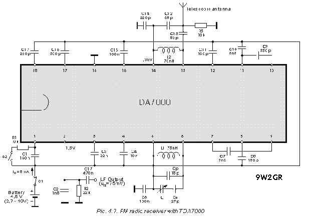
capacitance of Cs should be reduced (to 15 pF, 10 pF etc.), or it should be short-circuited. You can also try compressing or stretching the L1 coil, etc. The setup of the oscillatory circuit is completed when with C=Cmax some station that operates on app. 88 MHz can be heard, and with C=Cmin the one that works on 108 MHz. The input circuit setup (it is connected between pins 13 and 14), is performed by tuning the receiver to some mid-range station (about 98 MHz). Then, the best possible reception is searched, by changing capacitances C13 and C12 and inductance L2.
[ Homebrew ] [ Homepage Utama ]